On the 18th March 2021, the Crest restoration project was presented with the NSW Wooden Boat Associations’ Hal Harpur Award. This video documents the presentation by Peter WIDDERS, the President of the WBA.
The launch of Crest
This video documents the official launch of Crest which occurred on March 10, 2020.
On the restoration of Crest
This video, screened in the pavilion near the Alf Settree boatshed on the March 10, 2020 – the day of the official launch of the Crest – highlights some the restoration work put into the Crest’s diesel engine, the foredeck, the stringers, the cabin seating, and the electricals.
Mention is also made of the efforts by staff and volunteers during the 6 years of the restoration as well fund raising including original artworks donated for auction and for use in Crest calendars.
CREST Bulletin July-Dec 2017
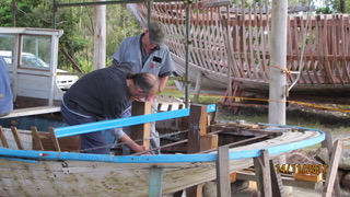
During the second half of 2017, CREST volunteers Brett, Dennis, Gary, Ian, James, Mike, Paul, Rob, Stan and Steve under the supervision of Dave Lewis, undertook the following restoration work ….
FOREDECK

Handrail
Mike, Rob & Stan applied black marine sealant between deck and base
of all 6 handrail supports before retightening securing bolts . . .
Mike removed the masking tape from around each of the supports . . .


WHEELHOUSE
Rob removed the layer of t&g planks on top which are not be replaced,
but the t&g planks below will be restored
")


Rob scraped back the layers of paint . . .


Mike carefully removed screws in need of replacement
on the wheelhouse windscreen frames . . .


attended to replacement stainless steel screws and silicon bronze nails,
ensuring countersinking of each. . .


….. Rob removed timber cover strip between wheelhouse shelf and cabin top …..


Having removed the timber cover strip, Stan scraped back the timber in preparation for replacement cover strip . . .


Mike and Stan continued with removing gal screws and replacing with brass screws . . .


Mike continued with replacement ss screws and silicon bronze nails on the cabin’s interior,


Stan completed the template for the replacement cover strip for the exterior where cabin meets front deck


Mike continued with delicate removal of fasteners in need of replacement
and of internal timber window surrounds …

Mike & Stan continued with removal of timber window trims (16 down – 7 to go) in need of replacement


. . . and made markings for replacement fullwidth trim piece.


Dave & Mike worked on getting the angles right for each of the corners for the first of 6 wheelhouse window internal surround pieces ..


")


Stan continued with shaping the timber strip to run along the underside of the front of the wheelhouse….


Mike & Rob combined efforts to sand and prepare the surrounds where 150-odd silicon-bronze or copper fasteners are now in place


to mix the epoxy filler

and to apply same to match the wheelhouse’s timber surfaces


Mike & Rob continued with the scraping and sanding of the infill covering of the new fasteners, as well as preparing the timber surfaces for later painting


Mike completed measurement and cutting of the dressed maple quad for the portside window


and made a start on the s’board window quad . .

Mike prepared 2 lengths,

then glued & screwed these to the s’board & port sides of the top of the wheelhouse . .


. . . at a later date a wooden handrail will be attached to these timbers utilising recently donated brass fittings.

Stan continued with shaping the single timber length to infill under the wheelhouse’s front edge


From mid-November, Mike, Rob & Stan

worked on cutting quad maple for the windows interiors

sanding back the shelf’s surfaces

shaping the wheelhouse’s exterior splash piece

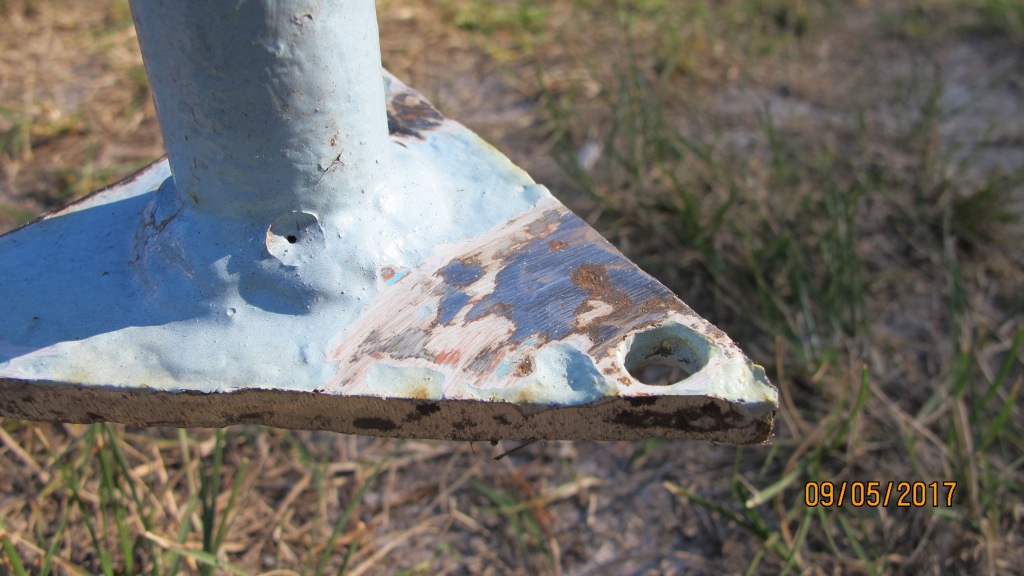
brushing preservative onto the splash piece and the interiors facing piece

and on the compression post’s bottom plate

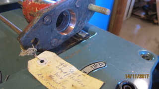
removed the engine room exhaust “stack”

Rob marked and cut out infill plugs for the chart table


and on top of the wheelhouse, Ian predrilled
 and nailed fasteners

to secure an interior batten to the top sheet of marine ply

Mike continued with the quad timber for the windows

Rob and Stan set the plugs in the chart-table


and nailed the quad trim between table and window board


During December, Mike continued with the internal window surround pieces and Rob with sanding back chart-table surfaces


Stan scraped the vertical face of the deck beam

the front face of the exterior sill
& applied marine filler as needed to seal the length of the interior quad trim


Mike continued with the internal window surround pieces

Rob with preparing chart-table surfaces

and helping Stan with shaping 2 infill lengths


which will fit behind the external sill-cover strip length..
CREST nameplate
In July, the CREST nameplate on the starboard side of the wheelhouse was removed and placed for safekeeping in the storeroom


Paint work
In mid-July, Rob started brushing blue gloss oil paint as overcoat on the faces of interior timbers – planks, stringers and ribs . . .


During August, after hand sanding the first coat, Rob completed the second overcoat . .


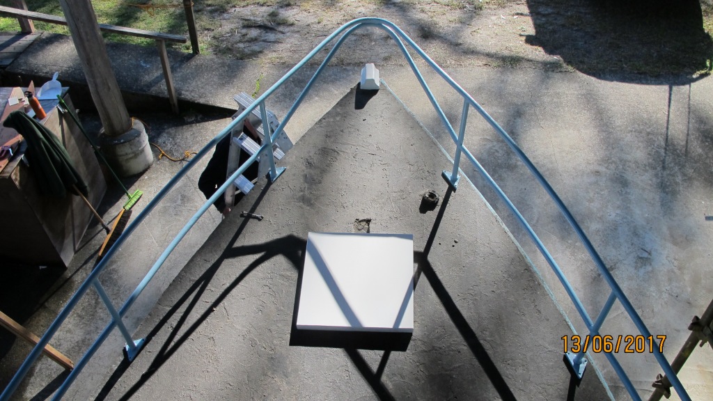
COMPRESSION POST
Because the Crest has a deck-stepped mast, a support, known as a compression post, is needed to fit the underside of the deck below the mast-step and the keel timber.
Stan has been working his magic on a shaping a length of oregon which will become the compression post, which will be octagonal in cross section and marine varnished to show its grains..


1911 penny
Earlier Stan had put out the call for a 1911 penny and in December Barry brought one in

The penny will be secreted at the base of Crest’s compression post when the time comes ..
1951 pennys
In late August, Paul removed 3 copper fasteners which had been used on the midships beam shelf starboard side and after cleaning the paint off the washers, 2 were revealed to be 1951 pennys.

Midship BRACE
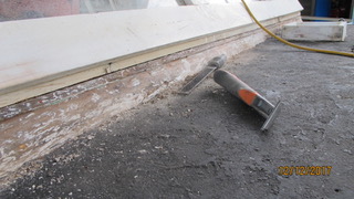
In September, it was decided that the midship brace needed to be removed and replaced. The existing brace, a galvanised iron bolt was replaced with 2 stainless steel rods which will be threaded and joined with a ss turnbuckle tensioner below deck.
2 photos below shows the gal bolt alongside the ss rods & tensioner . .


Paul sliding port side ss rod into position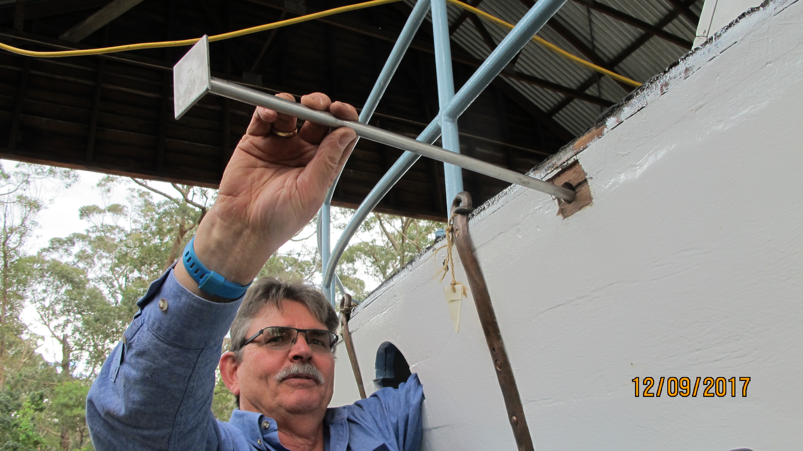
and adjusting the tensionser below deck

PORTHOLES
In August, Stan took on the job of chasing up replacement glass for the 2 brass portholes before they are re-attached to the hull ..


CHAIN PLATES
Also in August, Gary made up new copper bolts, complete with head and thread, and then secured the refurbished chainplates to the hull…


and at the end of August secured the bow’s chain plate . . 
BREASTHOOKs
A breasthook has the function of securing the hull’s port and s’board sides where they meet at the bow and is placed across the stem. The Crest has 2 breasthooks – one, of timber, at the level of the first stringer, and the second, of metal, at the second stringer.
In December, Ian shaped the spotted-gum timber needed to hold the hull’s refurbished galvanised iron breasthook when it is secured back in place ..


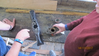
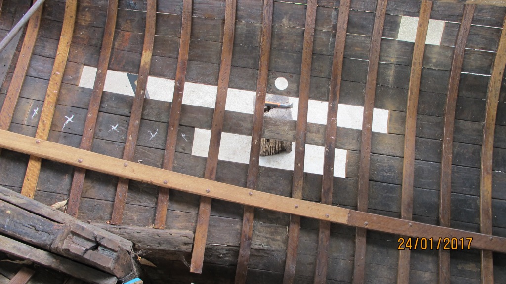
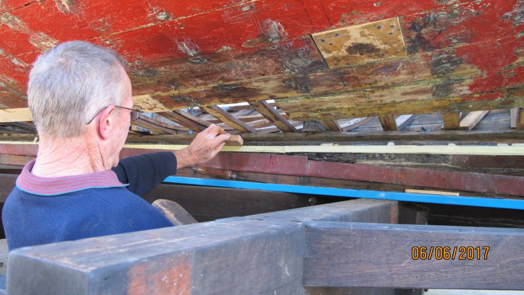
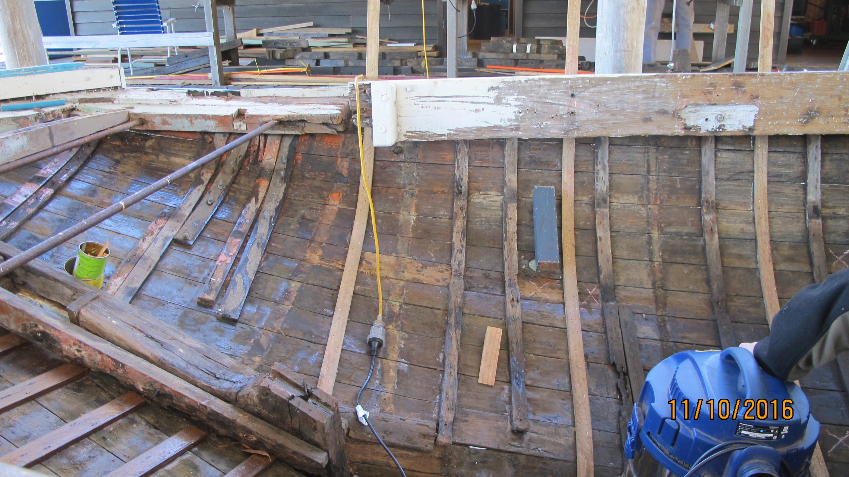
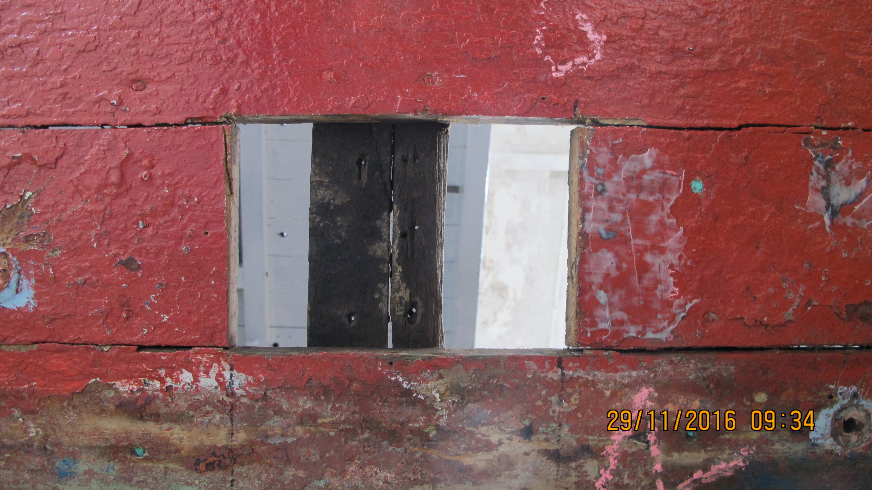
KEEL-RIB infills
In the space between where each set of ribs meet on the keel, an infill is required. One such space can be seen in the photo below.
 There are 40 pieces needed and are to be made from spotted gum timber.
In August, Gary, having worked out the measurements,
made a start on making the pieces using a 6metre length of spotted gum which had been milled some 12 months previously.
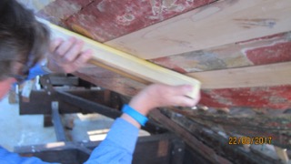
The sequence of photos below show the steps gone through . .
. . the timber length is marked up ….


…..cut length-wise on the portable bench saw . .

. . . put through the thicknesser . . .

then, up at the Museum’s workshop shed, cut precisely lengthwise vertically into two pieces,


then, after thicknessing to 16mm, marked out,

. . and cut into the sections as required . .


Each infill must be precisely fashioned for where it goes . .

and then treated in marine preservative . . .

. . .dried . . .
. . . positioned .. . 
. . . and secured . . .
PLANKS
From July onwards, Gary took on the job of measuring up and making the replacement planks. The number of planks to be replaced at this stage is 4 on each side of the keel – a total of 8. Each had to be made from Fijian Kauri and scarfing (overlapping) is required.
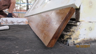
Before continuing with the replacement planks, Gary shaped a short length of softwood (1st photo) to make the replacement stopwater* which is a dowel driven into the hole drilled in the joint of the keel and the deadwood (which are both hardwood) at the level of the rabbet line. (2nd and 3rd photos) Because this is below water line, the softwood swells when wet and helps to ensure no seepage between the timbers at that joint.
*Stopwaters are also known as trunells (an abbreviation of tree nail) and are most commonly used to fasten planks to ribs and/or frames.


For the replacement portside garboard plank, Gary shaped the veneer template then matched it to the Kauri pine length before cutting to shape


Gary continued with cutting, planing and shaping the 2 lengths of Kauri which will make up the new garboard,


and started on the 5.7metre long veneer template for the 4th plank on the s’board


and in August, Gary checked the veneer template for the 4th plank on s’board,

")
before removing and laying it on 25mm thick Kauri,

then, after marking up the key positions with ruler and compasses along its length,


lightly hammered in nails at those positions before laying fairing batons against the nails,


and drawing profile lines top and bottom, before cutting with electric jigsaw or rotary saw


Once cut, Gary then put the plank through the thicknesser to reduce to 20mm.


In August, Paul took on sanding back the faces of new planks which are sitting slightly proud of existing . . .


ensuring fasteners (brass screws & copper nails) were countersunk on the new planks . .


. . to allow for sanding of the new timber. . .
In October, Paul started preparing a short section on the underside of the keel just in front of the rudder post where an infill piece is required to match the face of adjacent planks. The tapering infill piece will be glued and secured.


Also in October, Gary made up the starboard garboard which will be in 2 sections with scarfing (overlapping) as needed …
first putting the kauri through the thicknesser ..

marking-out from previously made template . .


temporarily securing flexible baton to draw the edge lines . .


then cutting the length just outside the edge line . .
 By mid October, Gary had completed the shaping and scarfing of the 2 lengths for the starboard garboard

RABBET
In October, work on setting the keel’s rabbet continued . .
On the portside amidship, Gary chamfered edges of the timber infill sections


after which 3part filler was mixed and applied to nooks and crannies between infills and keel timber . .

. . . and then a 3metre veneer length cut to which a slightly longer pine baton was air-gun stapled . .


… and then shiny-brown packing tape applied to the veneer’s surface along the length . .

. . before clamping the veneer, tape side up, against the ribs.


The clamping enables the filler to be held where most needed while it sets.
Once set and dried, the filler is cleaned and sanded . .


Gary continued these steps for the rabbets on both sides of the keel until the end of the year


The reason for setting the rabbets correctly is to ensure that the garboard planks will fit flush with the keel timber.
STERNPOST
In October, Paul started scraping down and cleaning up the the sternpost’s bearing adaptor piece . . . which had been removed sometime ago.


This piece attaches to the aft of the sternpost on the underside of the keel, and has the propellor shaft through it.


That part of the original sternpost above the keel line was previously removed.
Brett spent sometime getting the shaping and positioning of its replacement piece,

so that it will key-in correctly with the extant sternpost . .


Dave and Brett finalised the position and the setting of the replacement stern post.


AFT BULKHEAD
Brett and Dave worked on getting dimensions and measurements of the replacement aft bulkhead.
Photo below shows the removed bulkhead and bollards (corner posts).

A horizontal reference line between coamings was established,
 then the distance between bulkhead and the rudder post measured

and Brett was able to give a thumbs-up for the dimensions and measurements … 
Later positioning with the coamings and rudder post were confirmed


and a start on making the replacement bulkhead from maple got underway . .
The first section to be made is the splashboard . .


which includes shaping of the bollards


Rudder post, Stern post, horn timbers, and washbox
These timbers were a priority in the second half of the year.
Running either side of, and attached to, the rudder post and the stern post are pieces known as horn timbers which function to support the overhang of the stern. And behind the rudder post is the wash box.
From early July, Brett, Paul and Dave set about preparing these pieces .
Brett and Paul, applying two-part filler and black marine sealant as needed, manoeuvred, propped and clamped the horn timbers, rudder post, and washbox into position, and when all aligned tightened the clamps . .


When the filler and the glue had dried, clamps and props were removed and brass screws were turned and copper nails hammered as needed . .


Brett and Paul continued with sealing the horn timbers, rudder post and wash box … this required mixing 3 part filler (resin:hardener:filler powder – 5:1:as needed) troweled into spaces as required. Brett also troweled filler onto those sections of the cockpits coamings previously scraped back and preserved.
")


COAMINGs
Repair and replacement of portside coaming first ..


Then, in October, the s’board coaming ….


FLOORs
Work on replacing all the floors continued ….. at the beginning of July, Barry, Ian and Dave checked on Ian’s templates for heights and alignments for each of first 6 floors


After which cutting, shaping, drilling, thicknessing continued …


")


By December, Barry, Ian and Stan were able to give the thumbs up to the shaping and positioning of 5 of the floors ….


Engine beds and bearers
Engine beds sit on top of the floors and bearers sit on top of the beds.
The photo below show the bearers and beds before removal in mid-2015.

In mid-2017 the decision was made to make replacement beds and bearers, and as with the floors to be of hardwood.
Over the ensuing weeks, Ian, Barry and Dave shaped, milled and cut 2 lengths to make up two new bearers.


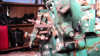
ENGINE
LISTER 3 cylinder diesel
Having got the Lister running in June, Steve continued with sorting
out a recalcitrant fuel pump and injector….

after which getting the governor to do what it should …

and in September having to sort out a minor leakage in 1 cylinder’s fuel line …
and in October successfully attached the flywheel drive gear …
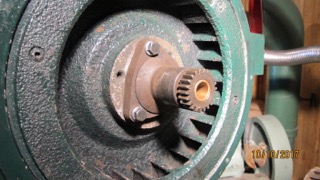
tapped (rethreaded) 8 bolt holes on the flywheel drive . .

and worked on the throttle . .

In November, the governor spring setting needed attention . .
as did how the aft shaft stuffing box and its interface with the sternpost adaptor piece which Paul was working on would be best achieved…

At the end of November, Steve had the engine running sweetly, its timing and the refurbished governor spring doing what they should …


and so another small milestone … the engine number ID plate attached.
OTHER NEWS
Having recently received sponsorhip from the Bendigo Bank Community Fund, members of the Bank were able to drop in and have a look at the work in progress in August. Dave and Gary can be seen hosting our visitors.


Thank you Bendigo Bank.
_________________________________________________________________________________
NEXT BULLETIN WILL COVER THE FIRST HALF OF 2018 AND THE ONGOING RESTORATION OF THE CREST.
CREST Bulletin Jan-June 2017
During the first half of 2017, CREST volunteers Brett, Dennis, Gary, Ian, James, Mike, Paul, Rob, Stan, Steve & Wendy, under the supervision of Dave Lewis, undertook the following restoration work . . .
HANDRAIL
In May and June, the handrail was taken down from temporary storage 
and Mike got to work on removing rust from the bases of the uprights ….
…… Gary welded the cut …..
…… kill rust was applied ….
…. the first coat of white undercoat applied . . .

….. and later applied the first blue overcoat ….
Painting completed, the handrail is now back where it was meant to be and is in the process of being secured – Mike is most happy . . .


HAND TOOLS
Former Alf Settree hand tools de-accessioned by the Museum’s Curatorial Management Centre to the CREST project are put into use …


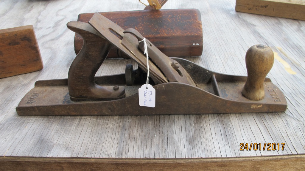
The ball peine hammer, shown below, is used for rounding the ends of cut-off copper nails over a copper washer…


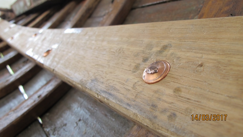
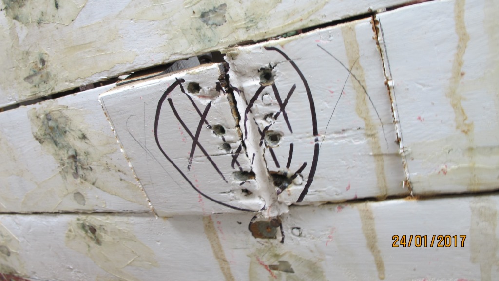
COIN washers
Brett recorded the internal positions of 3 coppercoin washers,
after removal from their stringer ……


BRASS PORTHOLES
Brett, having removed the last of the brass portholes last week, returned today with the aft s’board porthole, looking new and shiny. Using a motorised buffer wheel and other implements, he had removed all the verdigris, and made it look like new.


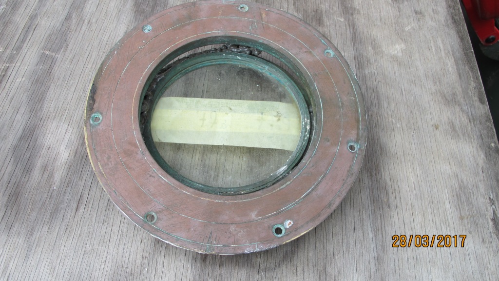
PORTHOLE GLASS
Later, Stan took measurements for the replacement glass.

RIBs
Paul cut and shaped a “v shaped” replacement rib … which will sit on top of an existing rib amidships .. the “v Shape” was a first for the project ..
achieved by matching the shape required without having to cut 2 short ribs ….


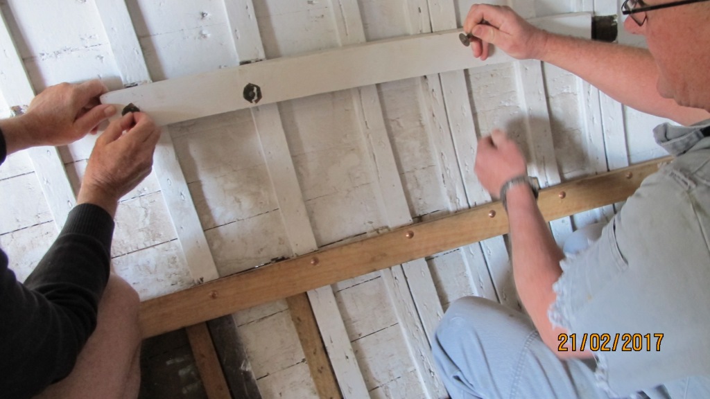
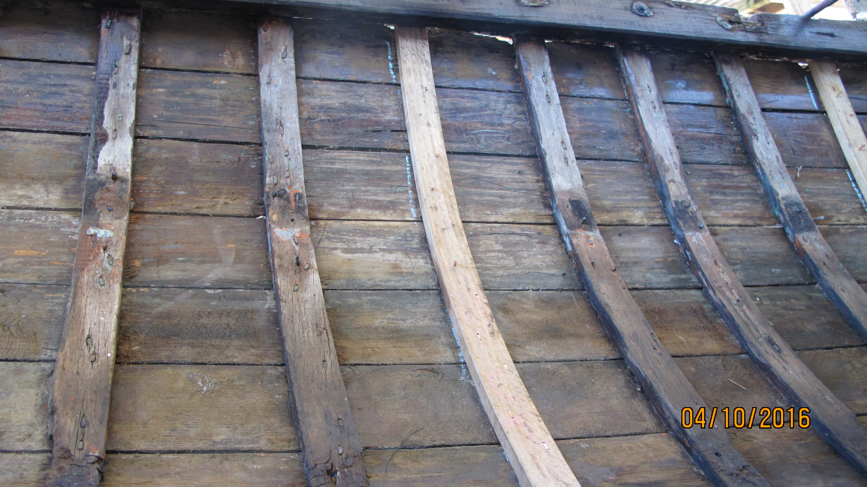
STRINGERs
Shaping and fastening by Brett of overlapping replacement stringer in January…


and in mid-March, another replacement 6.3m stringer – steamed, twisted, positioned, drilled, nailed and roved – went in


At the end of March, all hands and feet under front deck for the 8ft long replacement stringer with 2ft overlapping chamfer, which was steamed then nailed….


Of the 16 securing nails, 4 were roved with the original copper pennies.
PLANKs
Gary removed 2 lengths of planks in need of replacement ….
Gary removed 2 lengths of planks in need of replacement ….


Ian prepared and replaced another plank butt-end …


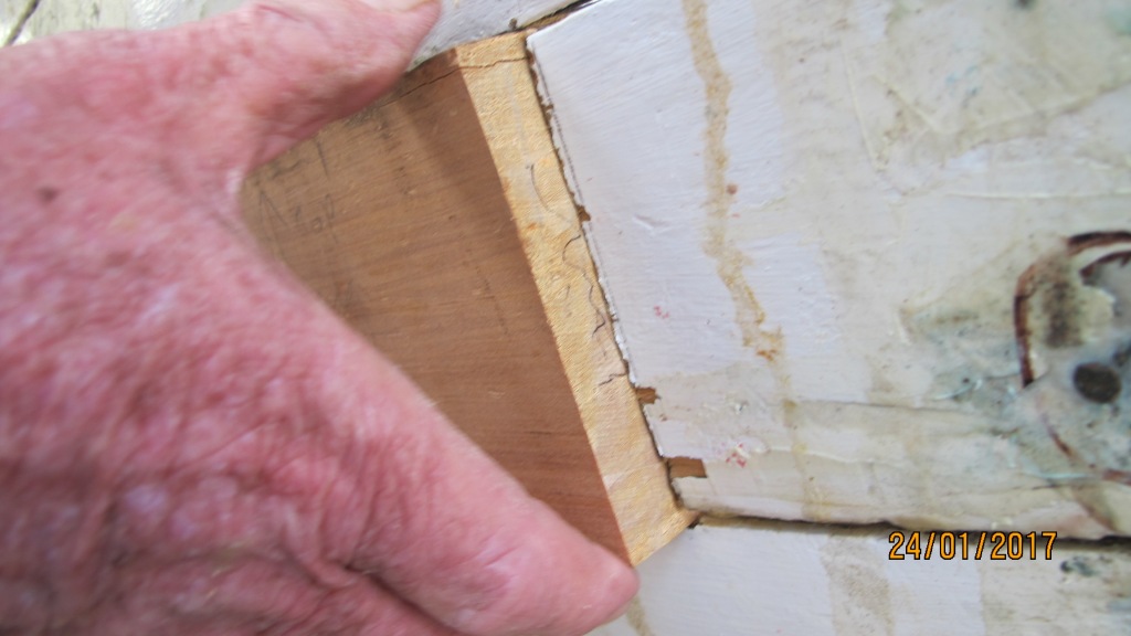
In late February, Ian completed his 16th plank-butt replacement – this is being second where the technique, as suggested by Gary, that the top face of the internal pieces (either side of the ribs) is curved and that there is a slight gap between the vertical face of these pieces with the ribs – in order to let water flow.


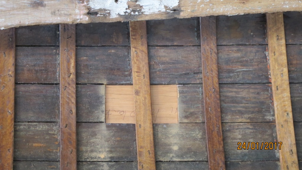
In March, Ian shaped, fitted & glued a replacement plug out of Kauri for a plank drain hole


Gary, using the spiling technique, drew up and shaped 2 Kauri replacement planks.
Spiling uses a smaller component as a pattern against which the outline of the larger component can be drawn and is often used for creating planks on traditionally built boats that have complex shapes. First, a piece of timber the same length as the desired plank but both thinner and narrower is cut. This is called the spiling batten.
The batten is then temporarily attached in the place of the removed plank . The shape required can then be traced onto the batten using a compass, or a dummy stick. The batten is then lifted out, placed on the new stock, and moved around to find the optimum use of the stock material, using the same compass or dummy stick, the exact shape required can be traced off the batten onto the new stock.


In early April, Gary shaped 2 replacement planks, 1 of which, at 2.3meters, (can be seen in the 2nd photo) is the longest to date . . .


GARBOARD planks
In early May, Dave and Gary made the decision that both port and starboard garboard planks – the planks either side the keel – will have to be removed and replaced … there has been too much damage to the rebate between their edges and the keel timber. Removing and replacing will be a big job but is necessary.
In early May, Dave and Gary made the decision that both port and starboard garboard planks – the planks either side the keel – will have to be removed and replaced … there has been too much damage to the rebate between their edges and the keel timber. Removing and replacing will be a big job but is necessary.
By the end of May, both planks, still pretty much intact, had been removed, and Gary had made a start on making up the template for the replacement garboards..


Barry used a wood thickness gauge to set the rebate line for the new garboard plank . . .

Plank replacement number 5
In mid-June, the 5th plank replacement went in . . . Gary fired up the steamer, heated the plank, and with the help of Brett, Dave, Mike, Ian, and James, propped, fine-trimmed, twisted and copper nailed it into position . . . .


FLOORs
In early April, Ian took on the big job of replacing all of the floors ….
6 of the original 7 floors shown below.

… the next 2 photos show floor 1 (the most forward) in position and its template


Over the next few weeks, Ian continued with making templates for the other floors …


The replacement floors to be made from iron bark.
WASH BOX
Also in April, Brett began work on the wash box timber refurbishment …

A wash box is the timber housing for the gal pipe in which the rudder stock sits..

Brett cut, sanded down and marked out the profile for the wash box replacement timber pieces, bench cut and the round planed to shape …


….. preservative brushed on …

Brett’s replacement wash box ready to be installed

and, new washbox in place….

PAINT
Applied undercoats and overcoats by Mike and Rob
…. external ……


. . . and internal . . .


LISTER Diesel motor
From early January to the end of June, Steve continued work on the Lister motor…
. .. setting the fuel supply . . .


… the tappets and the timing . . .

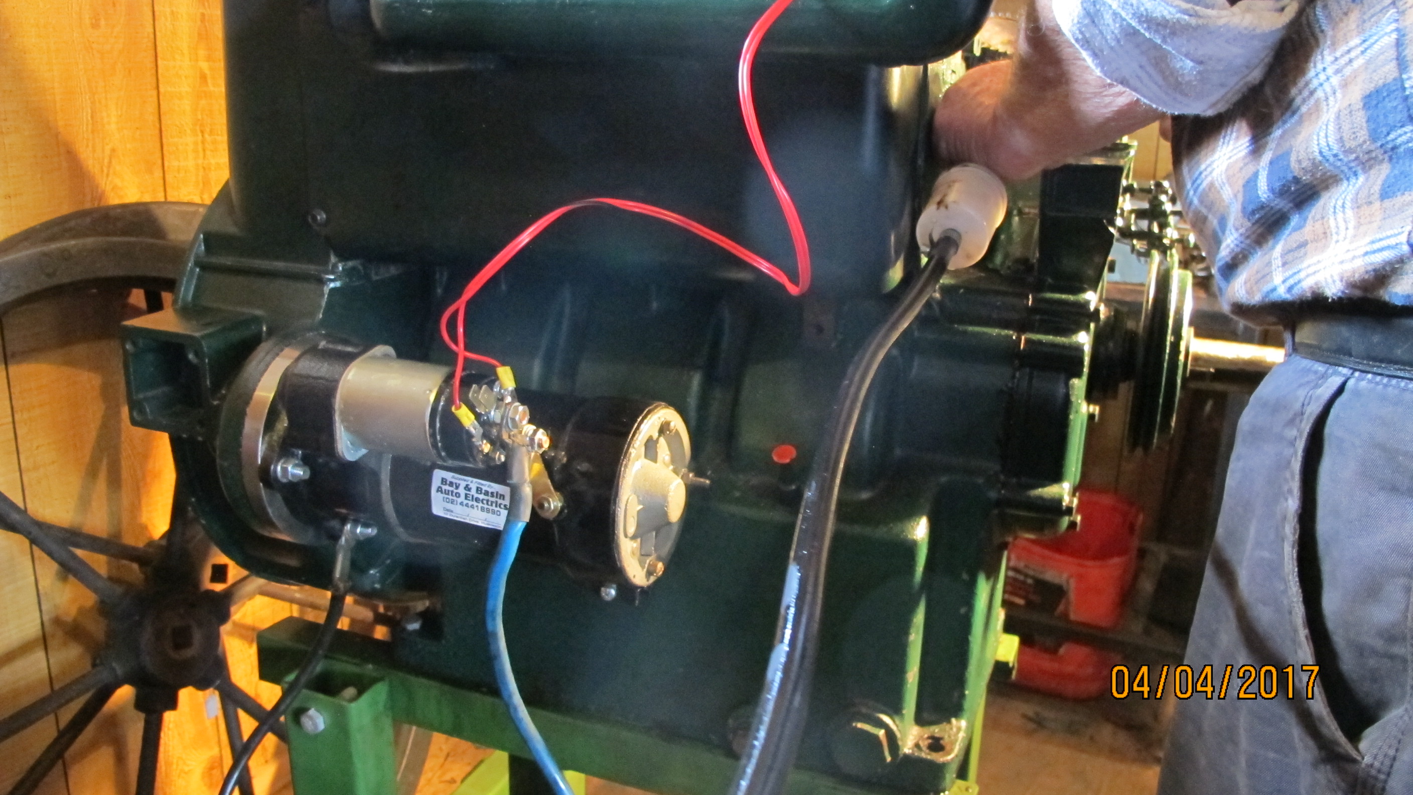
…. and in February, fitted the starter motor, which had been refurbished by
Bay&Basin Auto Electrics,


and in early April, Steve kicked over and ran over the Lister, …
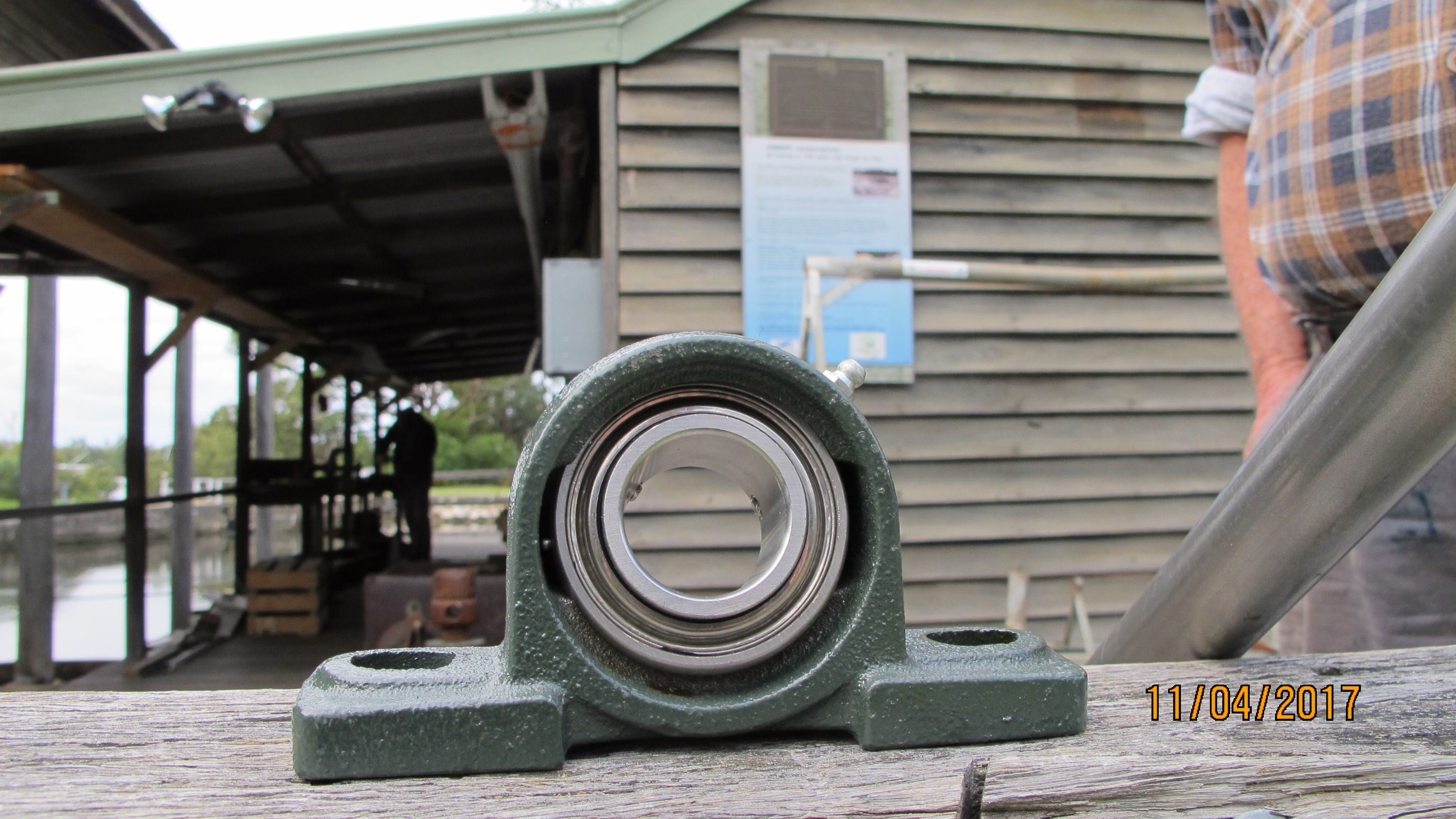
and next week checked with Dave the replacement propellor drive shaft and one of the ss ball bearings and its housing …..

and in May, fine tuning fuel supply, in particular the choke …

and later, having repaired the timing mechanism in his home workshop,

re-attached it, connected the starter motor and got the Lister running a lot smoother …

OTHER EVENTS
Surprise at smoko, just after the cookies run out, Nerole arrived with precisely 8 homemade pineapple tarts, delicious . . . much appreciated.

ANMM visit
In mid-March, the Museum and the Crest project was paid a visit by David Payne. David is Curator of Historic Vessels at Australian National Maritime Museum, and through the Australian Register of Historic Vessels, works closely with heritage boats in Australia – researching and advising on the craft and their social connections. David also documents many of the ANMM’s vessels with extensive drawings, and which includes the CREST.
Photo below shows from left – volunteers Stan & Gary, then David Payne, ANMM, Diana, JBMM Director, Dave Lewis, Graham Hinton JBMM CMC Manager, and John Ferguson, JBMM President.

Below, Crest’s supervising restorer David Lewis shows David Payne 1 of the floors recently removed from the Crest. 
CREST PROJECT SPONSORSHIP
On the last Tuesday of June, the CREST crew were most pleased to hear that their application to the Bendigo Bank under their Community Grants scheme was successful!
Many thanks to Ian, the Museum and to the CREST crew.
____________________________________________________________________________________________
CREST restoration Bulletin Sept-Dec 2016
During the last 4 months of 2016, weeks 35 to 51, Crest volunteers Brett, Dennis, Gary, Ian, James, Mike, Rob, Stan, Steve & Wendy, under the supervision of Dave Lewis, undertook the following restoration work . . .
FOREDECK
Mike completed the application of coats of bituflex to the foredeck ….


and later used a Teflon coated domestic iron to heat and smooth the bituflex …


Then, using the 60year-old rethreaded and cleaned copper bolts,


the replacement tabernacle was positioned and fastened to the foredeck …

RUDDERPOST
Wendy fashioned, glued and sanded wedges for the rebuild of a section of the replacement rudderpost 


RIBS
Brett and Stan, with assistance from Wendy and James, prepared, steam heated, and fitted 4 replacement ribs on the port side …


and later removed 5 more ribs and prepared (cleaning, plugging and preserving) for the replacement ribs….

then steamed, shaped and nailed 3 replacement ribs portside aft ….

and then steamed and nailed 4 replacement ribs portside aft ….

…. and then chalked ribs which are to be removed later .…
Stan & Wendy removed 7 ribs, filled ensuing nail holes portside aft …. making ready for new ribs next week …


…. which were made by Brett who took spotted-gum lengths up to the Museum’s Maintenance shed, where with Eugene’s assistance, cut 22 lengths,
brought them back for thicknessing for ribs for portside aft …
and later, the trimming of replacement ribs (port side) ….
STRINGERs
3 replacement stringers s’board side secured . .
and roved . . 
Portside full length replacement stringer nailed.
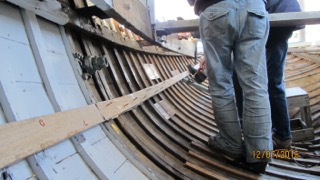
First photo shows drilling the marked-in-pink-chalk nail holes at the bow – these holes could not be drilled from inside. All nails hammered from outside.

1 stringer to go before the replacement floors (engine bed timbers) go in.
PLANKs
Ian shaped and secured replacement section at bow of the 2nd plank . .


. . . and midway along the 5th portside plank


Lister Diesel ENGINE
Steve continues his magic on tappets and timing ….

… as well as fabricating the spacer (thus saving some $500) which fits between starter motor and flywheel.
On Tuesday 11th October, week 41, the rebuilt Lister diesel was started for the first time since 1987 … Dave wound the crank handle as many times as needed,

…. while the one and only Steve worked his magic on the fuel mixture.
PROPELLLOR SHAFT
Steve started on the propeller’s drive shaft ….
and cleaning up of potential replacement prop-shaft holder …
Project Donors and Sponsor
Donated Scaffolding On Tuesday September 20th, week 38, Dane, Kingfisher restoration supervisor, helped out Crest restoration with delivery and assembling of donated scaffolding courtesy of Shoalhaven Scaffolding Services.
Much appreciated….
IMB Sponsor visit
On Tuesday 23 November, week 47, Kellie of the IMB paid the Crest a visit


End of bulletin
____________________________________________________________
Bulletin for August 2016
During August, Brett, Dave, Dennis, Gary, Ian, James, Mike, Rob, Stan, Steve and Wendy, undertook work on
PLANKS
Ian finalised his 6th plank end replacement piece . .


and, later, ran a fresh length of kauri through the thicknesser for the upcoming plank-end replacements …

which will include this one ….
and these plank end abutments . . 


RIBS
With Dave, Rob & Mike inside and Gary, Wendy, Ian & James outside, 3 replacement ribs just fwd of mid-ships were steamed and nailed …


and the following week, with Wendy, Gary, Stan & James outside, and Dave, Rob & Mike inside, 2 replacement ‘sister-ribs‘ just fwd of mid-ships were steamed and nailed …
Later, Stan & Rob carefully removed 3 ribs …
before ….
during . . 
after. . . 
with a side journey `which required removal of a circular plug in one plank …


LISTER DIESEL
Steve tackled fuel pump timing set-up …


Then the setting of tappets,


the tappet covers, . . . 

and of adjustment of decompression levers …

Making CREST’s permanent cradle trolley
Originally produced in early 2014, this was the first informational video about the CREST and its restoration. The video, narrated by the supervising boatbuilder, Dave Lewis, documents the construction of the trolley on which the hull’s permanent cradle will sit.
The CREST’s restoration is sponsored by the IMB Community Foundation.
CREST’s temporary lifting frame and cradle
Originally produced in 2014, this informational video documents the construction of the CREST’s temporary lifting frame and cradle.
July 2016 Bulletin
Restoration activity on the CREST over the last 6 weeks has included
TIMBER
STRINGERS
A significant event – the first replacement stringer now in place.
A brief description of the steps …
This stringer is one of 2 full-length 8.4metre 65 x 28 stringers on the starboard side, it required roving at each of the 40 ribs (frames) and the scarfing of 2 sections:-
The first section (at the bow) is held in place while holes, drilled from the outside, go through the plank, the rib and the timber of the new stringer.


Then a 2.5inch long copper nail is tapped through.


Photo below shows rove, a square-shanked copper nail and the ss rove-punch.
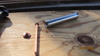
The rove-punch is used to tap the rove down the shaft of the nail until the rove is gripping the stringer’s surface.


The protruding nail shaft is then cut-off,

before the small-roundhead hammer, using rapid tapping, is used to shape the cut-nail shaft around the top of the rove.

At the plank’s outside surface, a nailhead sized counterweight applies pressure while the rapid tapping happens.

For the aft length of the replacement stringer, epoxy glue is applied to the .5metre long scarfing (overlap) section,


before this second length goes through the holding, drilling, nailing and roving process.

Photos below show the new stringer – viewed looking to the bow and to the stern.


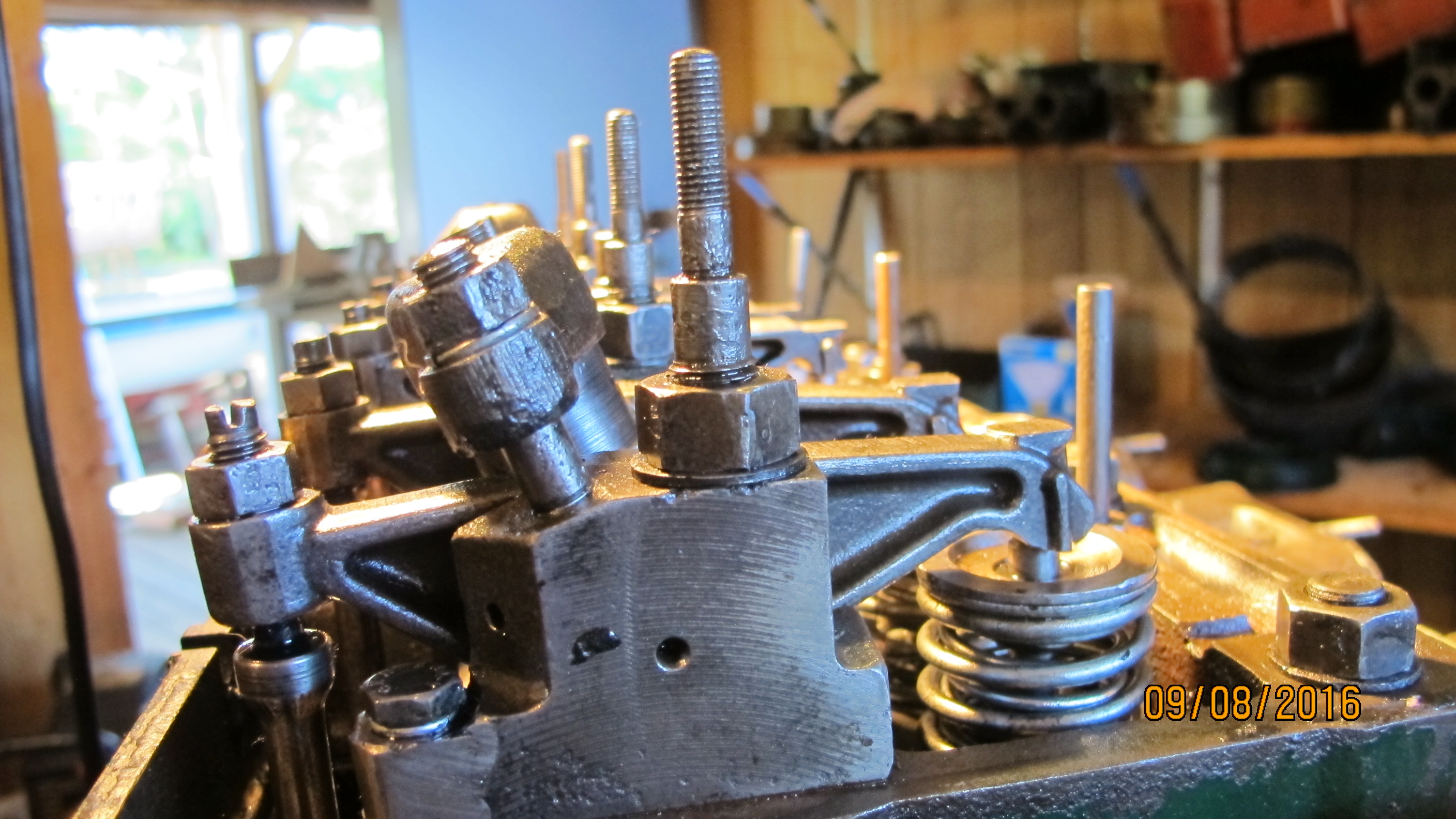
ENGINE
The system relief-valve has been refurbished and installed …

… as have the tappet rockers and …

… the exhaust manifold.

Refurbished oil strainer in-situ in sump.

___________________________________________________________________________________________
