During the second half of 2017, CREST volunteers Brett, Dennis, Gary, Ian, James, Mike, Paul, Rob, Stan and Steve under the supervision of Dave Lewis, undertook the following restoration work ….


")


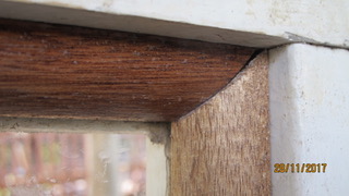
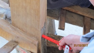
Having removed the timber cover strip, Stan scraped back the timber in preparation for replacement cover strip . . .


Mike and Stan continued with removing gal screws and replacing with brass screws . . .


Mike continued with replacement ss screws and silicon bronze nails on the cabin’s interior,


Stan completed the template for the replacement cover strip for the exterior where cabin meets front deck


Mike continued with delicate removal of fasteners in need of replacement
and of internal timber window surrounds …

Mike & Stan continued with removal of timber window trims (16 down – 7 to go) in need of replacement


. . . and made markings for replacement fullwidth trim piece.


Dave & Mike worked on getting the angles right for each of the corners for the first of 6 wheelhouse window internal surround pieces ..


")


Stan continued with shaping the timber strip to run along the underside of the front of the wheelhouse….


Mike & Rob combined efforts to sand and prepare the surrounds where 150-odd silicon-bronze or copper fasteners are now in place


to mix the epoxy filler

and to apply same to match the wheelhouse’s timber surfaces


Mike & Rob continued with the scraping and sanding of the infill covering of the new fasteners, as well as preparing the timber surfaces for later painting


Mike completed measurement and cutting of the dressed maple quad for the portside window


and made a start on the s’board window quad . .

Mike prepared 2 lengths,

then glued & screwed these to the s’board & port sides of the top of the wheelhouse . .


. . . at a later date a wooden handrail will be attached to these timbers utilising recently donated brass fittings.

Stan continued with shaping the single timber length to infill under the wheelhouse’s front edge


From mid-November, Mike, Rob & Stan

worked on cutting quad maple for the windows interiors
sanding back the shelf’s surfaces
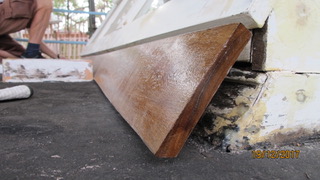
shaping the wheelhouse’s exterior splash piece

brushing preservative onto the splash piece and the interiors facing piece

and on the compression post’s bottom plate

removed the engine room exhaust “stack”
Rob marked and cut out infill plugs for the chart table


and on top of the wheelhouse, Ian predrilled
 and nailed fasteners

to secure an interior batten to the top sheet of marine ply

Mike continued with the quad timber for the windows
Rob and Stan set the plugs in the chart-table


and nailed the quad trim between table and window board


During December, Mike continued with the internal window surround pieces and Rob with sanding back chart-table surfaces


Stan scraped the vertical face of the deck beam

the front face of the exterior sill

& applied marine filler as needed to seal the length of the interior quad trim


Mike continued with the internal window surround pieces

Rob with preparing chart-table surfaces

and helping Stan with shaping 2 infill lengths


which will fit behind the external sill-cover strip length..
CREST nameplate
In July, the CREST nameplate on the starboard side of the wheelhouse was removed and placed for safekeeping in the storeroom


Paint work
In mid-July, Rob started brushing blue gloss oil paint as overcoat on the faces of interior timbers – planks, stringers and ribs . . .


During August, after hand sanding the first coat, Rob completed the second overcoat . .


COMPRESSION POST


1911 penny
Earlier Stan had put out the call for a 1911 penny and in December Barry brought one in

The penny will be secreted at the base of Crest’s compression post when the time comes ..
1951 pennys
In late August, Paul removed 3 copper fasteners which had been used on the midships beam shelf starboard side and after cleaning the paint off the washers, 2 were revealed to be 1951 pennys.

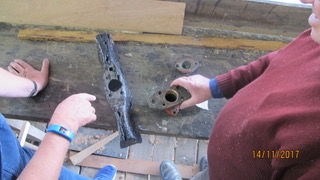
Midship BRACE
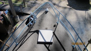
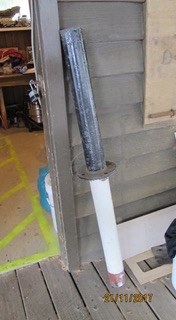
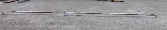
In September, it was decided that the midship brace needed to be removed and replaced. The existing brace, a galvanised iron bolt was replaced with 2 stainless steel rods which will be threaded and joined with a ss turnbuckle tensioner below deck.
2 photos below shows the gal bolt alongside the ss rods & tensioner . .

Paul sliding port side ss rod into position
and adjusting the tensionser below deck

PORTHOLES
In August, Stan took on the job of chasing up replacement glass for the 2 brass portholes before they are re-attached to the hull ..


CHAIN PLATES
Also in August, Gary made up new copper bolts, complete with head and thread, and then secured the refurbished chainplates to the hull…


and at the end of August secured the bow’s chain plate . . 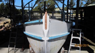
BREASTHOOKs
A breasthook has the function of securing the hull’s port and s’board sides where they meet at the bow and is placed across the stem. The Crest has 2 breasthooks – one, of timber, at the level of the first stringer, and the second, of metal, at the second stringer.
In December, Ian shaped the spotted-gum timber needed to hold the hull’s refurbished galvanised iron breasthook when it is secured back in place ..


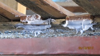
KEEL-RIB infills
In the space between where each set of ribs meet on the keel, an infill is required. One such space can be seen in the photo below.
 There are 40 pieces needed and are to be made from spotted gum timber.
In August, Gary, having worked out the measurements,
made a start on making the pieces using a 6metre length of spotted gum which had been milled some 12 months previously.
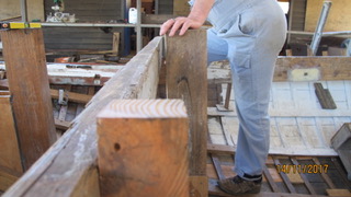
The sequence of photos below show the steps gone through . .
. . the timber length is marked up ….


…..cut length-wise on the portable bench saw . .

. . . put through the thicknesser . . .

then, up at the Museum’s workshop shed, cut precisely lengthwise vertically into two pieces,


then, after thicknessing to 16mm, marked out,

. . and cut into the sections as required . .


Each infill must be precisely fashioned for where it goes . .

and then treated in marine preservative . . .
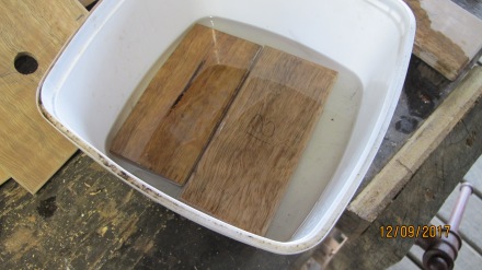
. . .dried . . .
. . . positioned .. . 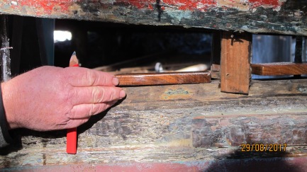
. . . and secured . . .
PLANKS
From July onwards, Gary took on the job of measuring up and making the replacement planks. The number of planks to be replaced at this stage is 4 on each side of the keel – a total of 8. Each had to be made from Fijian Kauri and scarfing (overlapping) is required.
Before continuing with the replacement planks, Gary shaped a short length of softwood (1st photo) to make the replacement stopwater* which is a dowel driven into the hole drilled in the joint of the keel and the deadwood (which are both hardwood) at the level of the rabbet line. (2nd and 3rd photos) Because this is below water line, the softwood swells when wet and helps to ensure no seepage between the timbers at that joint.
*Stopwaters are also known as trunells (an abbreviation of tree nail) and are most commonly used to fasten planks to ribs and/or frames.


For the replacement portside garboard plank, Gary shaped the veneer template then matched it to the Kauri pine length before cutting to shape


Gary continued with cutting, planing and shaping the 2 lengths of Kauri which will make up the new garboard,


and started on the 5.7metre long veneer template for the 4th plank on the s’board


and in August, Gary checked the veneer template for the 4th plank on s’board,

")
before removing and laying it on 25mm thick Kauri,

then, after marking up the key positions with ruler and compasses along its length,


lightly hammered in nails at those positions before laying fairing batons against the nails,


and drawing profile lines top and bottom, before cutting with electric jigsaw or rotary saw


Once cut, Gary then put the plank through the thicknesser to reduce to 20mm.


In August, Paul took on sanding back the faces of new planks which are sitting slightly proud of existing . . .


ensuring fasteners (brass screws & copper nails) were countersunk on the new planks . .


. . to allow for sanding of the new timber. . .

In October, Paul started preparing a short section on the underside of the keel just in front of the rudder post where an infill piece is required to match the face of adjacent planks. The tapering infill piece will be glued and secured.


Also in October, Gary made up the starboard garboard which will be in 2 sections with scarfing (overlapping) as needed …
first putting the kauri through the thicknesser ..

marking-out from previously made template . .


temporarily securing flexible baton to draw the edge lines . .


then cutting the length just outside the edge line . .
 By mid October, Gary had completed the shaping and scarfing of the 2 lengths for the starboard garboard

RABBET
In October, work on setting the keel’s rabbet continued . .
On the portside amidship, Gary chamfered edges of the timber infill sections


after which 3part filler was mixed and applied to nooks and crannies between infills and keel timber . .
. . . and then a 3metre veneer length cut to which a slightly longer pine baton was air-gun stapled . .


… and then shiny-brown packing tape applied to the veneer’s surface along the length . .

. . before clamping the veneer, tape side up, against the ribs.


The clamping enables the filler to be held where most needed while it sets.
Once set and dried, the filler is cleaned and sanded . .


Gary continued these steps for the rabbets on both sides of the keel until the end of the year


The reason for setting the rabbets correctly is to ensure that the garboard planks will fit flush with the keel timber.
STERNPOST
In October, Paul started scraping down and cleaning up the the sternpost’s bearing adaptor piece . . . which had been removed sometime ago.

This piece attaches to the aft of the sternpost on the underside of the keel, and has the propellor shaft through it.


so that it will key-in correctly with the extant sternpost . .


Dave and Brett finalised the position and the setting of the replacement stern post.


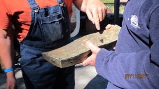
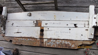
AFT BULKHEAD
Brett and Dave worked on getting dimensions and measurements of the replacement aft bulkhead.
Photo below shows the removed bulkhead and bollards (corner posts).
A horizontal reference line between coamings was established,
 then the distance between bulkhead and the rudder post measured
and Brett was able to give a thumbs-up for the dimensions and measurements … 
Later positioning with the coamings and rudder post were confirmed


and a start on making the replacement bulkhead from maple got underway . .
The first section to be made is the splashboard . .


which includes shaping of the bollards


Rudder post, Stern post, horn timbers, and washbox
These timbers were a priority in the second half of the year.
Running either side of, and attached to, the rudder post and the stern post are pieces known as horn timbers which function to support the overhang of the stern. And behind the rudder post is the wash box.
From early July, Brett, Paul and Dave set about preparing these pieces .
Brett and Paul, applying two-part filler and black marine sealant as needed, manoeuvred, propped and clamped the horn timbers, rudder post, and washbox into position, and when all aligned tightened the clamps . .


When the filler and the glue had dried, clamps and props were removed and brass screws were turned and copper nails hammered as needed . .


Brett and Paul continued with sealing the horn timbers, rudder post and wash box … this required mixing 3 part filler (resin:hardener:filler powder – 5:1:as needed) troweled into spaces as required. Brett also troweled filler onto those sections of the cockpits coamings previously scraped back and preserved.
")


COAMINGs
Repair and replacement of portside coaming first ..


Then, in October, the s’board coaming ….


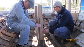
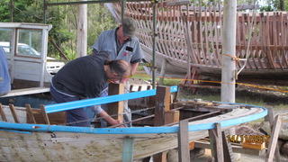
FLOORs
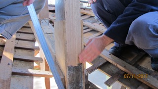
Work on replacing all the floors continued ….. at the beginning of July, Barry, Ian and Dave checked on Ian’s templates for heights and alignments for each of first 6 floors


After which cutting, shaping, drilling, thicknessing continued …


")


By December, Barry, Ian and Stan were able to give the thumbs up to the shaping and positioning of 5 of the floors ….


Engine beds and bearers
Engine beds sit on top of the floors and bearers sit on top of the beds.
The photo below show the bearers and beds before removal in mid-2015.

In mid-2017 the decision was made to make replacement beds and bearers, and as with the floors to be of hardwood.
Over the ensuing weeks, Ian, Barry and Dave shaped, milled and cut 2 lengths to make up two new bearers.


ENGINE
LISTER 3 cylinder diesel
Having got the Lister running in June, Steve continued with sorting
out a recalcitrant fuel pump and injector….

after which getting the governor to do what it should …

and in September having to sort out a minor leakage in 1 cylinder’s fuel line …

and in October successfully attached the flywheel drive gear …

tapped (rethreaded) 8 bolt holes on the flywheel drive . .

and worked on the throttle . .

In November, the governor spring setting needed attention . .

as did how the aft shaft stuffing box and its interface with the sternpost adaptor piece which Paul was working on would be best achieved…


At the end of November, Steve had the engine running sweetly, its timing and the refurbished governor spring doing what they should …


and so another small milestone … the engine number ID plate attached.
OTHER NEWS
Having recently received sponsorhip from the Bendigo Bank Community Fund, members of the Bank were able to drop in and have a look at the work in progress in August. Dave and Gary can be seen hosting our visitors.


Thank you Bendigo Bank.
_________________________________________________________________________________
NEXT BULLETIN WILL COVER THE FIRST HALF OF 2018 AND THE ONGOING RESTORATION OF THE CREST.
